FeedbackLoopDetector
Academic approach. (This device is only for research and has...
- Type
- Instrument
- Author
- CharlyBeck
- Version
- 0.1
- License
- AttributionNonCommercialNoDerivatives
- Live version
- 10.1.9
- Max version
- 8.1.3
- Downloads
- 181
- Updated
- 2020-05-01
Description
Academic approach. (This device is only for research and has no benefit/functionality for users)
This device detects feedback loops in a signal matrix/signal flow graph definition.
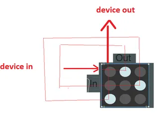
How the signal flow matrix works:
Following rules apply for this signal matrix:
- Left side are inputs
- top side are outputs
- In1/Out1 is the main input/output of the device
- The rest of the in/outs are internal routings
- The internal output is connected to the appropriate internal input
- So for n > 1 applies: out[n] is connected to in[n]
- This is why feedback loops may occur if the wrong routing is activated by setting the dot in the matrix.
How i plan to use this:
Later, for each dot in the matrix there will be one "subdevice" which can instanciate a vst plugin.
Using the signal matrix the order and paralel processing of the plugins can be redefined by simply changing the buttons in the matrix.
Comments (2)
i'm not sure if i understood correctly, but i think the clear answer is: this variant of the algorithm does not deal with audio levels. it just detects feedback loops and provides the disabled state for the matrix controll so a user can not produce such a feedback loop.
the 2nd point is, that i stopped the approach in m4l. instead i created a clr wrapper for coding max externals in c#.
I put a brief description of the project here:
https://karlchenscoderdasein.blogspot.com/2020/05/a-dynamic-signal-flow-graph.html
In the project the feedback loop detection is implemented in c#. This is way simpler than doing it m4l. Aside it didn't work correctly because ableton live has problems if the m4l patch is recursive.